Insert

You can insert beam parts to the model. Normally, you select the required part size from a list that is based on the available sizes in the beam specification or, in case of an out-of-spec part, in the Catalog Part, but if the part uses instance parameters you can define each dimension of the beam separately.
Inserting a beam
You can use the Insert tool to insert beam parts with or without a beam specification. During the insertion, you can rotate or mirror the beam, change the routing reference point, and trim the beam ends.
The program tries to keep the inserted beam parallel to the main planes by ignoring very minor deviations in the direction. That is, the beam is inserted parallel to the main axis if the direction vector is within the tolerance value defined in the project setting Tolerances > Maximum deviation from connection direction.
Do the following:
-
Optionally, use the Model Tree pane to select the system of the new beam.
-
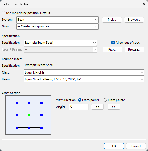
Select the Structural tab > Beam group > Insert. The Select Beam to Insert dialog opens.
-
Select the system of the beam.
-
Select whether to assign the beam to an existing or new group.
-
Select the beam specification with one of the following methods:
-
Specification – Select the specification from the drop-down list.
-
Recent Beams – Select a recently inserted beam from the drop-down list.
-
Pick – Pick the specification from another model object.
-
Browse – Select a beam profile from the object browser.
If the beam part to use is not defined in a specification, select the Allow out of spec option.
-
-
If you did not select a beam from Recent Beams, select the beam's class and size from the respective drop-down lists.
-
Cross Section shows the cross-section of the selected beam profile and the points that can be used as reference points when routing the beam part.
-
You can change the view direction of the preview image by selecting either From point1 or From point2.
-
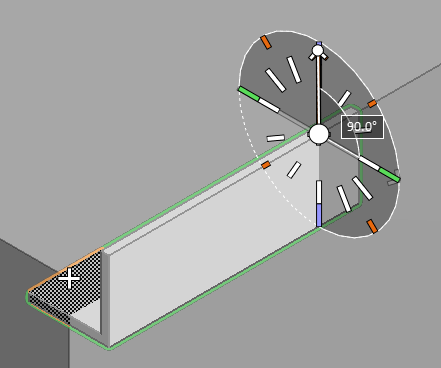
You can rotate the beam by specifying the specific rotation angle or by clicking either << or >> to rotate the profile by 45 degrees at a time. (You will be able to rotate the beam also when routing the beam, or after the insertion.)
-
The default reference point is at the center of the bounding box of the beam profile. You can change the reference point by clicking the point that you want to use.
-
-
Click OK.
-
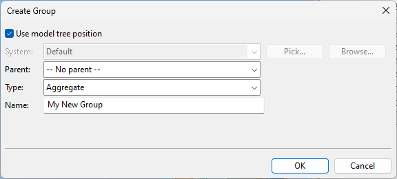
If you chose to create a new group, the Create Group dialog opens. Define the properties of the group to be created, and click OK.
-
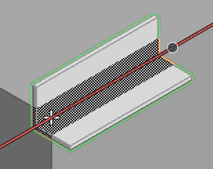
Define the start point of the route.
-
Navigate to the intended starting point.
-
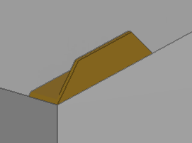
You can make an end cut to the beginning of the beam by selecting End cutting normal (N), defining the direction of the end normal, and pressing Space to accept. See also Defining direction in a view.
-
Click or press Enter to accept the starting point.
-
-
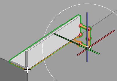
Move the mouse to start routing the beam in the intended direction. A preview of the beam is shown in the work view.
-
You can change the routing reference point, for example, to align a particular edge of the beam with the face or edge of another model object: select Select reference point (B), select the new reference point from the on-screen tool, and press Enter.
-
You can rotate the part: select Rotate (Alt+R), rotate the part with the on-screen tool, and press Enter.
-
You can mirror the part by selecting Mirror (Alt+M).
-
Define the end point of the route.
-
Navigate to the intended end point.
-
You can make an end cut to the end of the beam by selecting End cutting normal (N), defining the direction of the end normal, and pressing Space to accept.
-
Click or press Enter to accept the end point.
-
-
If the beam's Catalog Part uses a Dimension Table that uses instance parameters, the Edit Beam Profile Dimensions dialog opens for specifying the dimensions of the beam. Set the parameters as described in Edit instance parameters, and click OK to continue.
The beam is ready.
-
You can continue to insert more beams of the same type or press Esc to exit the tool.
About beams and instance parameters
Most beam parts represent standard structural steels that are fabricated in a predefined range of profile sizes. These standard sizes are defined in the Dimension Table of the beam part, and when a designer is inserting a beam to the model, the program shows the available sizes, based on the Catalog Part reference of the beam part.
Some beams, however, are created on-site by welding steel plates together, and there might be a very large number of different profile sizes that are supported via this method. Instead of listing every possible size variation in the Dimension Table separately, beams that are welded from plates can be defined using instance parameters.
Instance parameters allow each individual dimension of the beam profile to be defined as a list of values, a min–max range, or as having no constraints. When a beam that uses instance parameters is inserted to the model, the beam gets default dimensions from the Dimension Table and the designer can adjust each dimension as appropriate. The dimensions can also be edited later, as described in Edit instance parameters.
Administrator should only enable instance parameters for beam profiles that do not represent any standard. For details, see Creating a dimension table.